As I've posted elsewhere, I'll be taking part in this years April Tools competition on April 30 in Madeira Park, BC. Basically, we're given a pile of unknown materials and 3 hours to build a small boat, which we then race around the harbo(u)r.
I've wanted to do this for years, and I'm getting quite excited about it. My team is registered under the very appropriate name The Archimedes Screwballs, should you be in the area (ha!) and want to stop by to cheer. As you almost certainly will not be in the area, I'll be posting pictures afterwards. And very possibly a video of one of us (me, I'm thinking) getting quite wet.
Tuesday, April 12, 2011
Wednesday, April 6, 2011
Lightbox
(This was actually a December project, but it was only recently permanently mounted, so you're hearing about it now.)
So, Lauren was living in a basement room. No windows. This made getting up in the morning quite difficult, as it was always pitch black in there. As I have a predilection for elaborate technological solutions, I suggested we should make a lightbox disguised as a window, lit with daylight bulbs. I've always enjoyed how psychologically powerful the trick of daylight-colored light coming through fake windows is. So that's what we did.

We found a nice antique stained glass window at an architectural salvage store. Originally I planned on adding drapes, but that was before finding such a gorgeous window to work with. It's mounted on a simple wooden box I made, with hinges at the top and a latch at the bottom.

The electronics are hidden inside. I probably should have gone with 4 banks of tubes, but even the really cheap units were a bit pricey. The box was finished with some ebony stain, which nicely matched the weathered, mildewed window frame.

I'm quite happy with the result, for such a simple build. It's hooked up to a power strip with a built-in programmable timer, so it turns on 15 minutes before the alarm goes off.
One caveat: It was recently discovered that napping in the evening with the lightbox on can really, really mess up your Circadian rhythms. You have been warned.
So, Lauren was living in a basement room. No windows. This made getting up in the morning quite difficult, as it was always pitch black in there. As I have a predilection for elaborate technological solutions, I suggested we should make a lightbox disguised as a window, lit with daylight bulbs. I've always enjoyed how psychologically powerful the trick of daylight-colored light coming through fake windows is. So that's what we did.
We found a nice antique stained glass window at an architectural salvage store. Originally I planned on adding drapes, but that was before finding such a gorgeous window to work with. It's mounted on a simple wooden box I made, with hinges at the top and a latch at the bottom.
The electronics are hidden inside. I probably should have gone with 4 banks of tubes, but even the really cheap units were a bit pricey. The box was finished with some ebony stain, which nicely matched the weathered, mildewed window frame.
I'm quite happy with the result, for such a simple build. It's hooked up to a power strip with a built-in programmable timer, so it turns on 15 minutes before the alarm goes off.
One caveat: It was recently discovered that napping in the evening with the lightbox on can really, really mess up your Circadian rhythms. You have been warned.
Tuesday, April 5, 2011
Full-scale hydraulics
As I've mentioned elsewhere, I'm giving up on the hexapod as a project for this year. It's just too complicated and expensive to pull off in that time. Instead I'm going to spend the summer working on the Kalamazoo, hopefully getting it into much better shape for the Burn this year.
That doesn't mean I've stopped working on the hexapod, however, just that I've changed the schedule. Prototyping of the hip joint continues with decent, if slow progress. Most recently I've switched out the teeny tiny hydraulic test platform for something a little bit beefier.

It was sold for powering dump truck bed lifts, with basically no documentation. I'm not sure exactly how many amps it wants, but it's a lot. It works well enough, though. Should be capable of about 1.3 gallons per minute, which is conveniently close to 1/6 the number I've calculated as being required for the entire system. So if a single leg can move at speed being run off this pump, that will be very promising.
The hip joint is really the key to the entire project, as far as I can see. The mechanical design is the trickiest, as unlike the other two leg joints the forces are all parallel to the pivot, making it want to bind. And this is where the top speed of the final device is determined. During a normal stride, the other two joints will only move through maybe 10 degrees, while the horizontal hip joint will travel through upwards of 90. It needs to be a low friction and fast moving.
When dealing with hydraulics, speed is a matter of flow rates. A pump can only move so much hydraulic fluid at pressure per unit time, and that determines how fast a given cylinder will move. The volume a cylinder needs to actuate is simply the area of the bore times the length of travel. The faster the pump can provide that volume, the faster the cylinder moves. Of course, the smaller the bore is, the less force it will apply. And the shorter the travel, the worse the lever moment will be for pivoting something. No free lunch, here or anywhere. Luckily, however, the force being applied by even a very narrow cylinder is much more than I should be needing!

So for this joint I wanted a narrow cylinder, with as short a travel as possible. After poking around online for awhile, I finally found one that was 1" bore by 4" travel. Tiny, but it should still be big enough to do the job. I don't really know, of course, but that's what empirical testing is for! And last night I started on that, hooking up the new pump to the old control valve and electronics and the new cylinder, mounting it for the first time on the prototype hip joint, and giving it a spin. And I managed to do it without either losing a finger or spraying gallons of hydraulic fluid around the garage!
In short, a very real success. That's a full-scale joint running with full-scale hydraulics at a reasonable speed. (Would result in a hexapod walking speed of 3+ mph, depending on the leg length. Though without the other two cylinders running, it's not a very fair test.) I need to get it running using the Arduino PID controller next, to get a sense of how bad the momentum effects are going to be. Assuming that looks good, it's on to prototyping the rest of the leg. Which probably means switching to cartridge valves, which means making a manifold, all kinds of fun stuff. But there are several smaller projects clamoring for my attention this month, so most of that will have to wait.
That doesn't mean I've stopped working on the hexapod, however, just that I've changed the schedule. Prototyping of the hip joint continues with decent, if slow progress. Most recently I've switched out the teeny tiny hydraulic test platform for something a little bit beefier.
It was sold for powering dump truck bed lifts, with basically no documentation. I'm not sure exactly how many amps it wants, but it's a lot. It works well enough, though. Should be capable of about 1.3 gallons per minute, which is conveniently close to 1/6 the number I've calculated as being required for the entire system. So if a single leg can move at speed being run off this pump, that will be very promising.
The hip joint is really the key to the entire project, as far as I can see. The mechanical design is the trickiest, as unlike the other two leg joints the forces are all parallel to the pivot, making it want to bind. And this is where the top speed of the final device is determined. During a normal stride, the other two joints will only move through maybe 10 degrees, while the horizontal hip joint will travel through upwards of 90. It needs to be a low friction and fast moving.
When dealing with hydraulics, speed is a matter of flow rates. A pump can only move so much hydraulic fluid at pressure per unit time, and that determines how fast a given cylinder will move. The volume a cylinder needs to actuate is simply the area of the bore times the length of travel. The faster the pump can provide that volume, the faster the cylinder moves. Of course, the smaller the bore is, the less force it will apply. And the shorter the travel, the worse the lever moment will be for pivoting something. No free lunch, here or anywhere. Luckily, however, the force being applied by even a very narrow cylinder is much more than I should be needing!
So for this joint I wanted a narrow cylinder, with as short a travel as possible. After poking around online for awhile, I finally found one that was 1" bore by 4" travel. Tiny, but it should still be big enough to do the job. I don't really know, of course, but that's what empirical testing is for! And last night I started on that, hooking up the new pump to the old control valve and electronics and the new cylinder, mounting it for the first time on the prototype hip joint, and giving it a spin. And I managed to do it without either losing a finger or spraying gallons of hydraulic fluid around the garage!
In short, a very real success. That's a full-scale joint running with full-scale hydraulics at a reasonable speed. (Would result in a hexapod walking speed of 3+ mph, depending on the leg length. Though without the other two cylinders running, it's not a very fair test.) I need to get it running using the Arduino PID controller next, to get a sense of how bad the momentum effects are going to be. Assuming that looks good, it's on to prototyping the rest of the leg. Which probably means switching to cartridge valves, which means making a manifold, all kinds of fun stuff. But there are several smaller projects clamoring for my attention this month, so most of that will have to wait.
Monday, March 14, 2011
Horizontal Hip Joint Prototype
I've been (slowly) working on the prototype design for the horizontal hip joint. This is by far the trickiest joint of each leg, as the ~500 pounds it needs to support will be torquing the bearing instead of being a clean radial load. It's also the limiting factor in the overall speed of the hexapod: in a normal walking gait, the other two joints will only move very slightly, while the horizontal hip joint will swing through 90 degrees of travel. The smoother the action is here, the faster the top speed is likely to be.

I decided to use car wheel hub bearing assemblies, as they are cheap and robust. After playing with one under very moderate load, I decided that I just didn't like the torque it was being put under. So I went with two, stacked one top of the other. Now all that torque is converted into a much nicer radial load within each bearing. You can get an idea of the arrangement in this rough sketch. (Except I grew the bearing support frames upside down, oh well.)

This is the completed prototype. (The large shelf is only there for testing purposes.) The action is very smooth, and while a bit tedious, making 6 of these would not be a problem. I'm quite happy with it. Unless some major problems are discovered in later testing, I think this design will work nicely. Making just one of them is giving me a greater appreciation of just how big this thing is going to be.

Here's a closeup of one of the bearing assemblies. They're simply bolted to plates which are welded to the support frames. Everything is under compression.

And here it is with about 175 pounds of static load on it, which it handled quite nicely. Once I get a better test stand for it, I'm hoping to do some tests with it loaded closer to the design goal of 500 pounds. I'm running out of large chunks of steel to hang off of it, though.
I decided to use car wheel hub bearing assemblies, as they are cheap and robust. After playing with one under very moderate load, I decided that I just didn't like the torque it was being put under. So I went with two, stacked one top of the other. Now all that torque is converted into a much nicer radial load within each bearing. You can get an idea of the arrangement in this rough sketch. (Except I grew the bearing support frames upside down, oh well.)
This is the completed prototype. (The large shelf is only there for testing purposes.) The action is very smooth, and while a bit tedious, making 6 of these would not be a problem. I'm quite happy with it. Unless some major problems are discovered in later testing, I think this design will work nicely. Making just one of them is giving me a greater appreciation of just how big this thing is going to be.
Here's a closeup of one of the bearing assemblies. They're simply bolted to plates which are welded to the support frames. Everything is under compression.
And here it is with about 175 pounds of static load on it, which it handled quite nicely. Once I get a better test stand for it, I'm hoping to do some tests with it loaded closer to the design goal of 500 pounds. I'm running out of large chunks of steel to hang off of it, though.
Saturday, February 19, 2011
Hydraulics
As part of the investigation in the feasibility of the hexapod project, I've spent the last month playing with a small hydraulics test system. The final system will need 18 actuators, all moving simultaneously and quickly, controlled fairly precisely. Is this possible? (Or, more the point, affordable on my budget?) It's an open question.
The first step was the hook up a small electric motor to a small cylinder and control if from an Arduino. This was done with a solenoid valve interfaced through a basic solenoid driver circuit.
Control of the valve is only one side of the equation, however. To move the joint to a specific position, you need to know where it is, so you know when to stop moving it! This requires an encoder. Out of curiosity I tried using a flex sensor -- I don't recommend it. They're super noisy. Much more promising was the AS5040 chip, which is a non-contact magnetic system. A friend had a test board which I could borrow. It worked much, much, much better. With the addition of a PID library, it was all more or less working.
So, I'm sure I can control the hydraulics as needed. At a much higher cost than I would like -- the valves are going to be at least $100 each! The next step is to rigorously spec out the entire system using real components. Specifically, the horizontal hip joint needs to be able to cycle fast enough, using a real cylinder, driven by a hydraulic pump supplying a realistic volume. The big question is determining just how much force will be needed there. I'll be prototyping the joint and performing empirical measurements with full loading over the next few weeks. And once I have that answer, I'll have a pretty solid guess of just how much this is all going to cost -- and thus if I can do it this year or if it will have to stretch into 2012.
Sunday, January 9, 2011
Etched brass fan
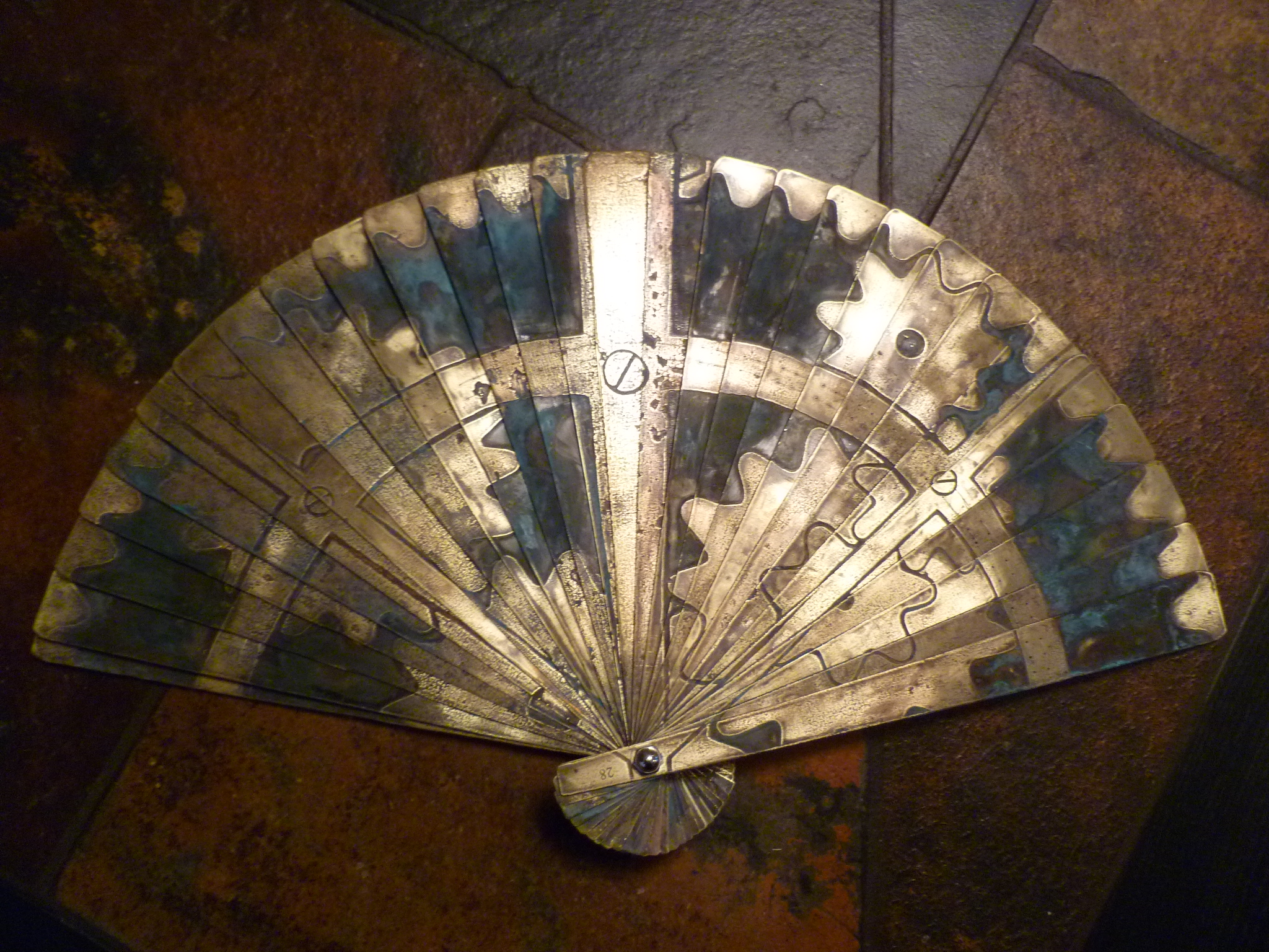
As part of vixy's costume for SteamCon this year, she needed a steampunk Asian-style fan. After some brainstorming, we decided to make one out of brass sheet, with a design etched on the front. This wouldn't be radically different from several other projects, though with 28 individual blades it would still be a significant amount of work.
The design itself was also a challenge, as it needed to be properly tiled across the blades. After some consultation on planetary gear systems, vixy drew it up in Photoshop and then cut it up into different layers using a template we worked out. In the end I was given a series of etching masks and set to work.

As previously mentioned, I first attempted the etching using a new (to me) galvanic process. The results were slow and uneven, and I was blowing through fuses on my power supply at an alarming rate. I finally gave up roughly halfway through and bought a large quantity of ferric chloride from VetCo. The rest of the etching was finished in a single night, thanks to the power of parallelism. Each blade was placed in a ziplock bag with a healthy does of ferric chloride and sealed up. All of these were then placed in a large plastic storage box. This contained the inevitable leaks, and also allowed me to gently agitate all of them at once through the simple expedient of holding it in my lap and bouncing my knees while watching a movie.

The results, once cut out, were pretty nice. This was the version shown at SteamCon, in fact, due to simply running out of time. But the etched pattern didn't really pop, and the folding/unfolding action was very stiff. The blades are threaded together with monofilament (see below), this is what lets you open the blades to the correct position. Unfortunately, the monofilament I had on hand turned out to be much thicker than I had realized. Not only did this make the action very clumsy, it also added a lot of fatigue on the monofilament and it started breaking within hours.

To fix the breaking problem, I bought much lighter, 4# monofilament. I also drilled a second line of holes in the blades, to add redundancy. Now it can break once in any place and still work.
To fix the pattern visibility, I needed to add a patina. I had attempted this originally using the same ammonia vapor technique that had worked well in the past. Those had all been on much smaller surface areas, however. Trying to do it on even half of the blades at once was painfully slow. After a pause of several weeks, I returned to the problem and decided to try using salt water, which I had read about as a way to improve the reaction. And it did! I made up a batch of saline (1 cup water, 2 tablespoons salt) and dabbed it onto the blades with a paper towel. These were suspended over an ammonia bath inside the same cheap plastic storage container used earlier. It only took about 30 minutes to get a very good patina on each blade. I had to come out every 15 minutes or so to reapply the salt water. Some blades too a lot longer, but as I was running them through in batches it still only took a couple of hours to get them all done.

The blades were then lightly sanded to remove the patine on the raised (unetched) sections of the design. They were bolted back onto the central pivot, and I faced the task of threading them all together. This was very difficult when threading the single line of thicker monofilament. Now that I was running two lines of much thinner monofilament, it was almost impossible to get the tensioning correct, leading to inappropriate spacing between blades when the fan was opened up. After some frustrating failures, I finally tried clamping the blades in place while working on it. Success! This prevented the tensioning on already threaded sections from coming loose, and it also made the entire this much easier to manage while working on it. It still took about two hours, but the result is quite satisfactory.

The original plans for this fan included wood slats on either end and a spring-loaded release mechanism. Those are now indefinitely on hold, as it has already taken far longer than planned, and the shear mass of that much brass is greater than expected. It's a fairly hefty artifact already, and adding to that seems unwise. Also, I'm very unsure making it spring-loaded is a good idea. The last thing I want to do is to break the monofilament and have to rethread it again. So for now, the etched brass fan is finished. Look for it next time vixy has an excuse to get dressed up!
Wednesday, December 29, 2010
Helpful holiday tip from your friends at Attoparsec
Don't leave ferric chloride sitting in an enameled steel container for months on end.

Cause, uh, it eventually will go somewhere else.
Cause, uh, it eventually will go somewhere else.
Subscribe to:
Comments (Atom)