Sunday, January 9, 2011

Etched brass fan


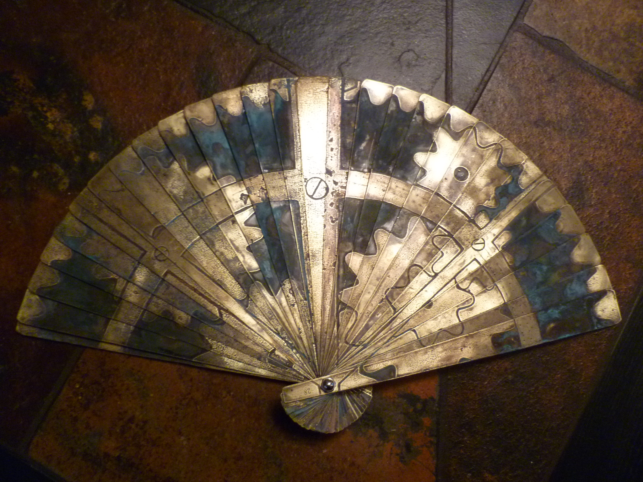
As part of vixy's costume for SteamCon this year, she needed a steampunk Asian-style fan. After some brainstorming, we decided to make one out of brass sheet, with a design etched on the front. This wouldn't be radically different from several other projects, though with 28 individual blades it would still be a significant amount of work.

The design itself was also a challenge, as it needed to be properly tiled across the blades. After some consultation on planetary gear systems, vixy drew it up in Photoshop and then cut it up into different layers using a template we worked out. In the end I was given a series of etching masks and set to work.


As previously mentioned, I first attempted the etching using a new (to me) galvanic process. The results were slow and uneven, and I was blowing through fuses on my power supply at an alarming rate. I finally gave up roughly halfway through and bought a large quantity of ferric chloride from VetCo. The rest of the etching was finished in a single night, thanks to the power of parallelism. Each blade was placed in a ziplock bag with a healthy does of ferric chloride and sealed up. All of these were then placed in a large plastic storage box. This contained the inevitable leaks, and also allowed me to gently agitate all of them at once through the simple expedient of holding it in my lap and bouncing my knees while watching a movie.


The results, once cut out, were pretty nice. This was the version shown at SteamCon, in fact, due to simply running out of time. But the etched pattern didn't really pop, and the folding/unfolding action was very stiff. The blades are threaded together with monofilament (see below), this is what lets you open the blades to the correct position. Unfortunately, the monofilament I had on hand turned out to be much thicker than I had realized. Not only did this make the action very clumsy, it also added a lot of fatigue on the monofilament and it started breaking within hours.


To fix the breaking problem, I bought much lighter, 4# monofilament. I also drilled a second line of holes in the blades, to add redundancy. Now it can break once in any place and still work.

To fix the pattern visibility, I needed to add a patina. I had attempted this originally using the same ammonia vapor technique that had worked well in the past. Those had all been on much smaller surface areas, however. Trying to do it on even half of the blades at once was painfully slow. After a pause of several weeks, I returned to the problem and decided to try using salt water, which I had read about as a way to improve the reaction. And it did! I made up a batch of saline (1 cup water, 2 tablespoons salt) and dabbed it onto the blades with a paper towel. These were suspended over an ammonia bath inside the same cheap plastic storage container used earlier. It only took about 30 minutes to get a very good patina on each blade. I had to come out every 15 minutes or so to reapply the salt water. Some blades too a lot longer, but as I was running them through in batches it still only took a couple of hours to get them all done.


The blades were then lightly sanded to remove the patine on the raised (unetched) sections of the design. They were bolted back onto the central pivot, and I faced the task of threading them all together. This was very difficult when threading the single line of thicker monofilament. Now that I was running two lines of much thinner monofilament, it was almost impossible to get the tensioning correct, leading to inappropriate spacing between blades when the fan was opened up. After some frustrating failures, I finally tried clamping the blades in place while working on it. Success! This prevented the tensioning on already threaded sections from coming loose, and it also made the entire this much easier to manage while working on it. It still took about two hours, but the result is quite satisfactory.


The original plans for this fan included wood slats on either end and a spring-loaded release mechanism. Those are now indefinitely on hold, as it has already taken far longer than planned, and the shear mass of that much brass is greater than expected. It's a fairly hefty artifact already, and adding to that seems unwise. Also, I'm very unsure making it spring-loaded is a good idea. The last thing I want to do is to break the monofilament and have to rethread it again. So for now, the etched brass fan is finished. Look for it next time vixy has an excuse to get dressed up!

Wednesday, December 29, 2010

Helpful holiday tip from your friends at Attoparsec

Don't leave ferric chloride sitting in an enameled steel container for months on end.


Cause, uh, it eventually will go somewhere else.

Sunday, November 14, 2010

Galvanic Etching

I've been working on a spring-loaded brass fan, which requires a lot of etching to be done. Normally I would do it chemically with ferric chloride, but that would get very expensive very quickly. So I decided to finally take the plunge and try out galvanic etching, generally following the guidelines here.


It has worked well enough, so far, but it's a bit of a messy process. With a bit under an inch between the work piece and the cathode, it takes 30-45 minutes to get a decent etch. Given that I have 28 pieces to do for the fan, this is only barely acceptable.

Gunk builds up on the cathode fairly quickly, which eventually bridges to the work piece and generates a short. I have to sit there with it and clean things off every 5 minutes. Possibly with a pump this could be improved. My power supply eventually blew its fuse, thanks to all the shorts.


The results are decent, but surprisingly rough in places. A ferric chloride etch would be much cleaner. Some of this seems to be the exact laser printer/glossy photo paper resist transfer process that I'm using. It starts to peel away towards the end of the etching process. The quality of the non-resist areas is really nice, though, giving a very smooth surface.

Thursday, November 4, 2010

Finished Lightsuit

As some of my cryptic Twitter updates have hinted at, I've been working on a el-wire suit. Only 10 months early for Burning Man 2011!

At its core is an Arduino Mega, a Memsic 2125 dual axis accelerometer, and 24 channels of independent el-wire control. All this is mounted on a faux-military jumpsuit. It has multiple modes of operation, including a motion-reactive setting which turns the entire thing into a bar graph showing the local acceleration.

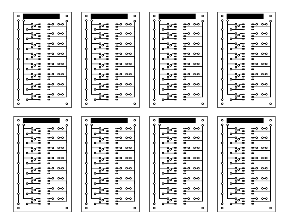
The el-wire control is based on the circuit described here. I etched 3 circuit boards, each with 8 channels of control. I've posted the SVG file for the boards here, should you want to use it. It uses the same components as in the link above.

And what does it look like? Something like this:


The battery held up for 5+ hours without any problems. A couple strands went dead, but I kind of expected that, given how delicate el-wire joints are. I'm hoping the failure rate will drop with time as the weak ones are replaced. It was reasonably comfortable to wear, though the el-wire attachment has to be improved. They were too loose and one on the ankle broke its stitching. I need to improve the programming on the accelerometer mode, adding some smoothing and non-linear scaling to the values. But not bad!

Wednesday, November 3, 2010

Difference Engine

A couple of weeks ago I was lucky enough to be able to visit the Difference Engine at the Computer History Museum. It would be safe to say that I considered it something of a pilgrimage.


I will assume anyone reading this knows the general history of the Difference Engine. In brief, a 19th century mechanical calculator that was never built at the time, but has since been proved to be quite practical. Mostly notable because Babbage went on to design the Analytical Engine, also never built, which would have been a general purpose computer in every modern sense of the term. This is as close to real steampunk as the world ever got.

The principle behind the Difference Engine is actually pretty simple. If you take any expression f(), you can create a list of output values. f(0) = a, f(1) = b, etc. You can then look at the differences between the output values, and the differences between the differences, and so on. At some point, if f() is a polynomial, these differences will become constant. For an example, let's look at f(x) = x^2 - 5x + 10.

xf(x)f(x)'f(x)''
0 10
1 6 4
2 4 2 2
3 4 0 2
4 6 2 2
5 10 4 2


Once we're looking at the difference of the difference (or the second derivative) we're looking at a constant value of 2 (which is what we'd expect, as f(x) is a second order polynomial). Neat, but so what? Well, now that we've worked this out, we can calculate further values of f(x) just using addition. We can now work right to left, adding f(5)'' to f(5)', and then adding that to f(5) and we get f(6)!

xf(x)f(x)'f(x)''
0 10
1 6 4
2 4 2 2
3 4 0 2
4 6 2 2
5 10 4 2
6 16 6 2


So that's pretty cool. And that's exactly what the Difference Engine does.


Each of those columns is a 31 digit number. There are 9 columns, allowing 9th order polynomials to be calculated. Adding is a very simple operation mechanically -- gears turning gears at a 1:1 ratio. The complication comes from carry operations, which is what the helices on the columns in this picture do. (This is the rear of the machine.)

With the mechanism so far, you can calculate some fairly complicated expressions with a high degree of reliability. But this is the 19th century. You're not calculating them for use in a ray tracing or something, you want to generate a big book of trig tables. Which means that all these values have to be typeset. By hand. Backwords. Needless to say, this can introduce a lot of errors. If you're obsessive enough to build a Difference Engine in order to generate accurate values, this situation simply will not do. Obviously you need to design a printer as well, which is exactly what Babbage did.


It isn't enough just to print onto paper (though it does do that), because then the values would still need to be transfered to type. So it also printed into a soft plaster sheet, creating a stereotype mold from which an entire page can be cast. No chance for human error.


Now, this is all stuff that anyone slightly obsessed with the history of the Difference Engine would know. What is particularly exciting about there being real working Engines in the world is that one can talk to the people who really use them and have real working knowledge of the things. Which is absolutely what I did.


This is the base of the printer. That crank wasn't on the original plans -- it turns out that the printer jams fairly easily, at which point you need to run it backwards separate from the main Engine. So they added a crank at that end, and a little clutch to disengage the printer.

Also, notice the little cable at the bottom? That gets pulled when the printer hits the end of the page, at which point a lot of stuff needs to be reset. The cable runs the length of the machine...


...finally coming out at the main crank, where it attaches to a clutch on the bevel gear. Thus, when the printer ends a page, the crank is disengaged and the person turning it knows to stop. (This was in the original design!) What wasn't in the original design was the 4:1 reduction gear on the crank itself. It just takes too much effort to turn otherwise, not something Babbage would have been able to tell in the design phase.

Speaking of the main crank, it turns out that turning it requires a lot of training, because the Engine requires very different amounts of force at different phases of a calculation cycle. And it jams fairly easily, so you need to know when to apply a lot of force, and when it shouldn't need much force so stop immediately.


Back at the printer, it has these escapement wheels and adjustment cranks. The left escapement defines how many columns are on a page, and the one of the right sets spacing between lines -- you can just see the short-short-short-short-long spacing in the wheels, which puts a larger space between every fifth line, which is what you'd want in a table of numbers to make lookup easier. The crank adjusts the overall spacing between lines.

Other cool stuff lacking in specific pictures:

Most of the bolts worked loose while it was on the cargo plane being delivered. It was built only with mid-19th century technology, so no lock-washers or Loctite was used. Because of this they have been fighting jams and problems ever since. They recently made a series of adjustments to the angular position of the take-off gears from the main drive shaft, which determines the relative timing of various operations in a computational cycle. They managed to do this because one of the museum employees happened to be visiting London and could stop by the other Difference Engine there and take some measurements.

The printer works, but they do not normally have it set up with ink or plaster. This is mostly because period ink is water based, and would have to be cleaned off immediately to prevent corrosion. The one thing that is not rigorously period is the lubricants used. Original ones would be horrible animal-based ones and just not worth it. Originally this Engine used petroleum lubricants, with an associated machine smell. Upon encountering it, the wife of the owner (who will eventually have it installed in his living room) said that it was not acceptable. Ever since, they have used FDA-approved food equipment lubricants, which are silicone based and have no smell at all.

The thing that impressed me most of all was finding out that the 31 computational digits can be split up into multiple calculations happening in parallel, with correspondingly fewer digits of precision. The Engine as it is set up at the museum is running in a 27/4 configuration. The larger set is calculating a 7th-order polynomial for demonstration purposes. The smaller set is set up with just a 1 in the first column. Which means that the output column is incremented by 1 every cycle. In modern terms: printf("%d", ++i); It's a debug statement! A convenient little printout that helps the operators keep track of what is going on! I was utterly charmed by it -- I bet Babbage never thought about doing that. This is the kind of thing that only gets discovered when you're actually using a system. It's a delightful little look into a parallel world where Babbage didn't get quite so perfectionistic and actually got the damn thing built.

Finally, here are some videos I took:


Tuesday, August 24, 2010

Final road test

The Kalamazoo is done, more or less. And it works, more or less.


It takes more effort to drive than I expected. The steering isn't very stable, despite the caster effect, which means I really only have one hand left to pump with. It's not going to be a very practical vehicle. Oh well.

I redid the horn mounting tonight, accounting for the change in primary driver position. Tomorrow I'll disassemble the entire thing and stain the wood. That's when I'll mount the etched brass builder's plate I made. I drive it to Spokane Friday after work in pieces, re-assemble it there, load it into my dad's Burning Man trailer, and head for the playa Sunday morning. Whew.

Sunday, August 22, 2010

Lanterns

When originally conceived, I planned on wrapping the Kalamazoo in el-wire. It's for Burning Man, after all, and everything there is wrapped in el-wire. But as work progressed, I kept adding more and more subtle, classy design details. By the time I got to seriously thinking about lighting, the idea of adding el-wire seemed really... tacky. I played with the idea of the solar-powered fake lanterns you can get as lawn decoration, which seemed to fit the evolved look better. But they're seriously not cheap, and, well, fake. So... why not real lanterns?

I ended up going with two at the front and two hanging under the pump-arm tripods. The forward pair hang from (custom, natch) smithed hooks. I went with a pigtail curlicue instead of the same 2D spiral I've used everywhere else. As well as adding some variety, this also helps control the swing of the lanterns.


The two under the pump arm hang from some cheap brass chain.


I let one of the lanterns burn for an hour tonight to gage fuel consumption. I put in 150 ml of oil at the beginning, and at the end I poured out... 150 ml of oil. So I don't think taking enough fuel will be a problem.

Road test #3 happened yesterday, with decent results. I tightened the chains today but didn't have an opportunity to take it out again. Running out of time to make modifications, but at least my to-do list is getting quite short.