While working on the design for a large Burning Man project, I was faced with a need to have a connecting rod coming off of a rocker arm, but to prevent a very complicated joint it could only pivot in one axis at each end. This was vexing, until I realized that this is not a new problem. No less a figure than James Watt himself faced something similar, when first moving from atmospheric to true steam engines where the piston pushed as well as pulled. The piston rod needed to be kept vertical, while the lever arm it was connected to needed to move in an arc. What to do?
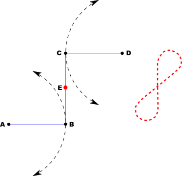
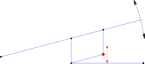
He came up with this, the Watt Linkage. Arms AB and CD pivot about their ends. But on the connecting link CB between them, there is a magic point E (its exact position depends on the ratio of AB to CD) whose motion is something very similar to the analemma-like shape to the right. If you keep the angular displacement of the main arms small compared to their length, E moves almost perfectly vertically. (Technically there is still some horizontal movement, but that's well below anything I'll be caring about. If you want perfection, go with the Peaucellier–Lipkin linkage.)
So, that's awesome, but how do you use it for a pump arm like I'm talking about?
You pantograph it! You pantograph the hell out of it! The same parts are there as before, but we've added another two links so that we can use the far corner instead of E. This is a lot easier to attach a piston rod to, and it keeps the tie rod connection close in to the main frame.
Rather charmed with this solution, I went ahead and prototyped it. Good thing, too, because it turns out I didn't really understand it very well to begin with! But further research and testing cleared things up.
As you can see in the video, the motion of E isn't perfectly vertical, because I didn't get the geometry of the linkages particularly great. But you can plainly see how much less its horizontal motion is compared to the pump rod itself. I'm not the world's biggest James Watt fan (everyone hates on Edison, when there are so many assholes in the history of science and technology to choose from!), but he really did make some amazing leaps of design. Props where props are due.