I've been working on a spring-loaded brass fan, which requires a lot of etching to be done. Normally I would do it chemically with ferric chloride, but that would get very expensive very quickly. So I decided to finally take the plunge and try out galvanic etching, generally following the guidelines here.
It has worked well enough, so far, but it's a bit of a messy process. With a bit under an inch between the work piece and the cathode, it takes 30-45 minutes to get a decent etch. Given that I have 28 pieces to do for the fan, this is only barely acceptable.
Gunk builds up on the cathode fairly quickly, which eventually bridges to the work piece and generates a short. I have to sit there with it and clean things off every 5 minutes. Possibly with a pump this could be improved. My power supply eventually blew its fuse, thanks to all the shorts.
The results are decent, but surprisingly rough in places. A ferric chloride etch would be much cleaner. Some of this seems to be the exact laser printer/glossy photo paper resist transfer process that I'm using. It starts to peel away towards the end of the etching process. The quality of the non-resist areas is really nice, though, giving a very smooth surface.
As some of my cryptic Twitter updates have hinted at, I've been working on a el-wire suit. Only 10 months early for Burning Man 2011!
At its core is an Arduino Mega, a Memsic 2125 dual axis accelerometer, and 24 channels of independent el-wire control. All this is mounted on a faux-military jumpsuit. It has multiple modes of operation, including a motion-reactive setting which turns the entire thing into a bar graph showing the local acceleration.
The el-wire control is based on the circuit described here. I etched 3 circuit boards, each with 8 channels of control. I've posted the SVG file for the boards here, should you want to use it. It uses the same components as in the link above.
And what does it look like? Something like this:
The battery held up for 5+ hours without any problems. A couple strands went dead, but I kind of expected that, given how delicate el-wire joints are. I'm hoping the failure rate will drop with time as the weak ones are replaced. It was reasonably comfortable to wear, though the el-wire attachment has to be improved. They were too loose and one on the ankle broke its stitching. I need to improve the programming on the accelerometer mode, adding some smoothing and non-linear scaling to the values. But not bad!
A couple of weeks ago I was lucky enough to be able to visit the Difference Engine at the Computer History Museum. It would be safe to say that I considered it something of a pilgrimage.
I will assume anyone reading this knows the general history of the Difference Engine. In brief, a 19th century mechanical calculator that was never built at the time, but has since been proved to be quite practical. Mostly notable because Babbage went on to design the Analytical Engine, also never built, which would have been a general purpose computer in every modern sense of the term. This is as close to real steampunk as the world ever got.
The principle behind the Difference Engine is actually pretty simple. If you take any expression f(), you can create a list of output values. f(0) = a, f(1) = b, etc. You can then look at the differences between the output values, and the differences between the differences, and so on. At some point, if f() is a polynomial, these differences will become constant. For an example, let's look at f(x) = x^2 - 5x + 10.
x
f(x)
f(x)'
f(x)''
0
10
1
6
4
2
4
2
2
3
4
0
2
4
6
2
2
5
10
4
2
Once we're looking at the difference of the difference (or the second derivative) we're looking at a constant value of 2 (which is what we'd expect, as f(x) is a second order polynomial). Neat, but so what? Well, now that we've worked this out, we can calculate further values of f(x) just using addition. We can now work right to left, adding f(5)'' to f(5)', and then adding that to f(5) and we get f(6)!
x
f(x)
f(x)'
f(x)''
0
10
1
6
4
2
4
2
2
3
4
0
2
4
6
2
2
5
10
4
2
6
16
6
2
So that's pretty cool. And that's exactly what the Difference Engine does.
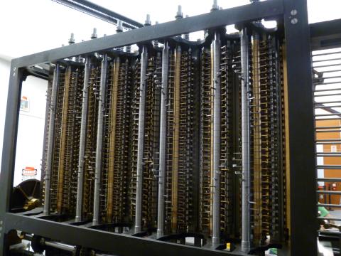
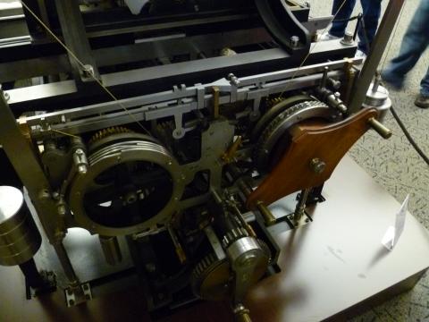
Each of those columns is a 31 digit number. There are 9 columns, allowing 9th order polynomials to be calculated. Adding is a very simple operation mechanically -- gears turning gears at a 1:1 ratio. The complication comes from carry operations, which is what the helices on the columns in this picture do. (This is the rear of the machine.)
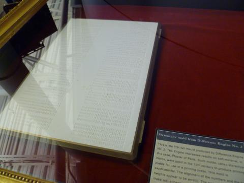
With the mechanism so far, you can calculate some fairly complicated expressions with a high degree of reliability. But this is the 19th century. You're not calculating them for use in a ray tracing or something, you want to generate a big book of trig tables. Which means that all these values have to be typeset. By hand. Backwords. Needless to say, this can introduce a lot of errors. If you're obsessive enough to build a Difference Engine in order to generate accurate values, this situation simply will not do. Obviously you need to design a printer as well, which is exactly what Babbage did.
It isn't enough just to print onto paper (though it does do that), because then the values would still need to be transfered to type. So it also printed into a soft plaster sheet, creating a stereotype mold from which an entire page can be cast. No chance for human error.
Now, this is all stuff that anyone slightly obsessed with the history of the Difference Engine would know. What is particularly exciting about there being real working Engines in the world is that one can talk to the people who really use them and have real working knowledge of the things. Which is absolutely what I did.
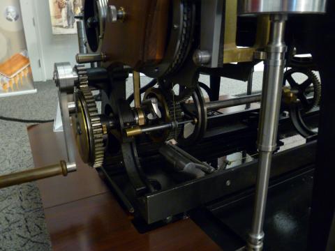
This is the base of the printer. That crank wasn't on the original plans -- it turns out that the printer jams fairly easily, at which point you need to run it backwards separate from the main Engine. So they added a crank at that end, and a little clutch to disengage the printer.
Also, notice the little cable at the bottom? That gets pulled when the printer hits the end of the page, at which point a lot of stuff needs to be reset. The cable runs the length of the machine...
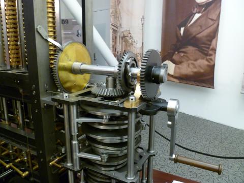
...finally coming out at the main crank, where it attaches to a clutch on the bevel gear. Thus, when the printer ends a page, the crank is disengaged and the person turning it knows to stop. (This was in the original design!) What wasn't in the original design was the 4:1 reduction gear on the crank itself. It just takes too much effort to turn otherwise, not something Babbage would have been able to tell in the design phase.
Speaking of the main crank, it turns out that turning it requires a lot of training, because the Engine requires very different amounts of force at different phases of a calculation cycle. And it jams fairly easily, so you need to know when to apply a lot of force, and when it shouldn't need much force so stop immediately.
Back at the printer, it has these escapement wheels and adjustment cranks. The left escapement defines how many columns are on a page, and the one of the right sets spacing between lines -- you can just see the short-short-short-short-long spacing in the wheels, which puts a larger space between every fifth line, which is what you'd want in a table of numbers to make lookup easier. The crank adjusts the overall spacing between lines.
Other cool stuff lacking in specific pictures:
Most of the bolts worked loose while it was on the cargo plane being delivered. It was built only with mid-19th century technology, so no lock-washers or Loctite was used. Because of this they have been fighting jams and problems ever since. They recently made a series of adjustments to the angular position of the take-off gears from the main drive shaft, which determines the relative timing of various operations in a computational cycle. They managed to do this because one of the museum employees happened to be visiting London and could stop by the other Difference Engine there and take some measurements.
The printer works, but they do not normally have it set up with ink or plaster. This is mostly because period ink is water based, and would have to be cleaned off immediately to prevent corrosion. The one thing that is not rigorously period is the lubricants used. Original ones would be horrible animal-based ones and just not worth it. Originally this Engine used petroleum lubricants, with an associated machine smell. Upon encountering it, the wife of the owner (who will eventually have it installed in his living room) said that it was not acceptable. Ever since, they have used FDA-approved food equipment lubricants, which are silicone based and have no smell at all.
The thing that impressed me most of all was finding out that the 31 computational digits can be split up into multiple calculations happening in parallel, with correspondingly fewer digits of precision. The Engine as it is set up at the museum is running in a 27/4 configuration. The larger set is calculating a 7th-order polynomial for demonstration purposes. The smaller set is set up with just a 1 in the first column. Which means that the output column is incremented by 1 every cycle. In modern terms: printf("%d", ++i); It's a debug statement! A convenient little printout that helps the operators keep track of what is going on! I was utterly charmed by it -- I bet Babbage never thought about doing that. This is the kind of thing that only gets discovered when you're actually using a system. It's a delightful little look into a parallel world where Babbage didn't get quite so perfectionistic and actually got the damn thing built.
The Kalamazoo is done, more or less. And it works, more or less.
It takes more effort to drive than I expected. The steering isn't very stable, despite the caster effect, which means I really only have one hand left to pump with. It's not going to be a very practical vehicle. Oh well.
I redid the horn mounting tonight, accounting for the change in primary driver position. Tomorrow I'll disassemble the entire thing and stain the wood. That's when I'll mount the etched brass builder's plate I made. I drive it to Spokane Friday after work in pieces, re-assemble it there, load it into my dad's Burning Man trailer, and head for the playa Sunday morning. Whew.
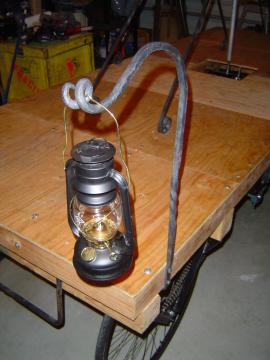
When originally conceived, I planned on wrapping the Kalamazoo in el-wire. It's for Burning Man, after all, and everything there is wrapped in el-wire. But as work progressed, I kept adding more and more subtle, classy design details. By the time I got to seriously thinking about lighting, the idea of adding el-wire seemed really... tacky. I played with the idea of the solar-powered fake lanterns you can get as lawn decoration, which seemed to fit the evolved look better. But they're seriously not cheap, and, well, fake. So... why not real lanterns?
I ended up going with two at the front and two hanging under the pump-arm tripods. The forward pair hang from (custom, natch) smithed hooks. I went with a pigtail curlicue instead of the same 2D spiral I've used everywhere else. As well as adding some variety, this also helps control the swing of the lanterns.
The two under the pump arm hang from some cheap brass chain.
I let one of the lanterns burn for an hour tonight to gage fuel consumption. I put in 150 ml of oil at the beginning, and at the end I poured out... 150 ml of oil. So I don't think taking enough fuel will be a problem.
Road test #3 happened yesterday, with decent results. I tightened the chains today but didn't have an opportunity to take it out again. Running out of time to make modifications, but at least my to-do list is getting quite short.
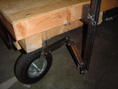
Spent the last week designing and building the new steering mechanism for the Kalamazoo. After last week's disastrous road test, it was critical that this problem be solved. And while what I came up with isn't pretty, it looks like it will work okay.
In short, I bolted on a lever to the side, which connects to the caster via a connecting rod and ugly universal joint system. The motion is actually pretty nice, even when stationary. (On a nice smooth concrete slab, anyway.) I need to offset the lever above the deck to make it easier for the driver to reach, but other than that it's a much nicer interface than I expected. That was always a driving motivation for the old differential braking system -- how do you pump and steer at the same time? While not perfect, the lever approach is pretty decent. And it feels very awesome. Part rudder, part steam locomotive control. Not bad.
Today's road test did conclusively show that only controlling one caster was not enough. Particularly with any back-and-forward motion it was very easy to get in a bad state where the uncontrolled casters was out of sync, sometimes to the point where the Kalamazoo was completely stalled. It will be easy enough to add a tie rod over to the other caster. I always figured this might be needed, but decided to be lazy and try it this way first. Very little work wasted.
The other big issue coming out of the first road test was the failure of my hacked-up fixie wheels under load. So this week I threw a gob of cash at the problem and bought new ones. Unfortunately, no one makes real 20" fixie wheels. But I got a system the bike store people thought might work. Today's road test showed that, no, it doesn't work. This leaves only one palatable option -- I need to switch to full size bike tires. I only went with 20" because I wanted to keep the deck lower for stability (less of a concern now that I've been on the thing for real) and because I was using 12" pneumatic casters in the front. I might just have to live with an A-Team-van-style raised back end, or shim the front casters by a few inches. We'll see.
Overall, while the broken fixies were a big disappointment, the second road test went pretty well. I was even able to drive (slowly, jerkily) up a slight slope, showing the gear ratio changes are helping. There might be one more improvement there, if an ebay shipment arrives in time. I also have a big hunk of lead strapped to the crankshaft to improve its flywheel effect, though I'm unclear how much that actually helps at these low speeds.
On the way back down to the garage I road it and mostly let gravity do the work while I steered and counter-pumped for braking. This worked great, until it got to the steep section and I had to navigate several parked cars. At one point the rear end lost its grip and I fishtailed most alarmingly towards a well. No control authority, just suddenly riding along on the world's stupidest surf board. Important lesson: don't drive the Kalamazoo obliquely across an incline.
Tony, Rob and I pushed the Kalamazoo up to the road from the garage today to do some real testing. As the video shows, the results were pretty bad.
Time for me to eat an entire murder of crows: differential braking for steering does not work here. At all. I now have a bit over two weeks in which to design and build something completely different.
The action is really jerky, with a massive clank at the top and bottom of the stroke. Haven't quite figured this out yet, might be related to slack in the chain drive. I know how to minimize the noise, at least, but I really want it running smoother than this.
Less seriously, but still annoyingly, we broke the fixed gear connection on one of the drive wheels. Hopefully I can just pay to get some real ones made up at Recycled Cycles. A cash-soluble problem, as I like to say. If that fails, I can always flip that one wheel around. It would break the symmetry of the drive chains (grrrr), but then it would be turning in the correct direction at least when driving forward. I cut the keyway extra long on that shaft precisely to handle this contingency.
I won't deny it, I'm now worried about getting this working in time. Particularly with the Laser Medusa Helmet work I also want to get done. Overall I'm really proud of the work so far, just have to get these last problems sorted out. We'll see...
Not a lot of visible progress after a very frustrating week. It's looking very encouraging that I'll have this thing finally working for real tonight or tomorrow, but I thought I'd share this today.
This week was a bit disappointing as not one but two shop trips failed to get the keyways cut for the sprockets. My hopes are high for another one this coming Saturday. If that one fails I'm going to have to put out an open plea on the local metal hobbyist list. I'm starting to feel the time pressure, despite still having a full month and really being fairly close to finishing. There are just several other things I need to work on before Burning Man as well as the Kalamazoo, such as the higher power Laser Medusa Helmet upgrade, or converting the old Self-Adjusting Electromechanical Goggles into a more comfortable leather goggle format. Busy, expensive month ahead!
There was still plenty of work done this weekend, though. Despite not having the keyways cut, I assembled the full drive train for the first time, including the drive wheel chains.
Took some time to adjust the differential shaft mounting to get proper tension on the drive wheel chains. This made the crankshaft chain too slack, but I'm going to add a simple idler for it. I need to order a selection of 1/2" sprockets anyway, as I'm quite sure I'm going to want to adjust the gearing ratio, and there is a very convenient set of mounting bolts available. Easy.
Yeah, I just love how this looks.
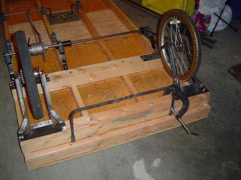
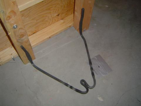
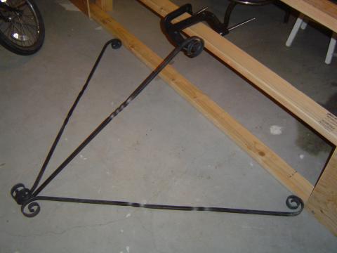
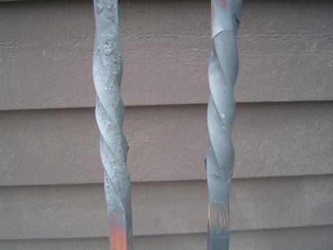
After the test of the platform elevated on all four wheels last week, I started thinking about how to make the Kalamazoo easier to use. It rolled around so easily that mounting it was a bit tricky. I'll probably add some kind of parking brake, but I decided it would also be nice to have a stair at either end so you don't need to make such a big dramatic step to get up on the deck. I spent about an hour with the forge tonight and ended up with a pair of rather handsome, if simple, 1/2" mounting rungs.
I couldn't resist adding a pretty little twist in the center, where it shouldn't get in the way. I'll bolt them on tomorrow. Which means I'll finally have the 4x4s on the ends removed and can fix the mounting of the decorative 2x4 end plates, which are currently bolted into T-nuts and just aren't very stable. That will be pleasing.
I'm starting to think about lighting for nighttime use. I don't think I want to put el-wire up the pump arm struts, it would just look too tacky during the day. After cruising the lawn lighting section at Lowe's, I'm pondering adding some wrought iron mounting hooks for solar-powered lanterns. Maybe one at each corner, and then one hanging under each pump arm tripod. Not very flashy, but it would go with the look a lot better. I'd still probably put a perimeter loop or two of el-wire around the platform, though, just for safety.
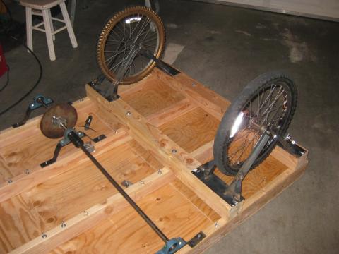
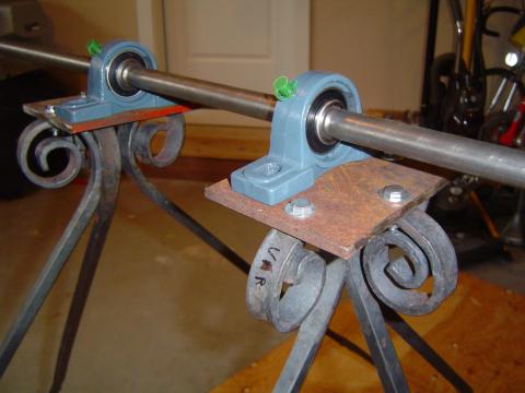
I finally mounted the pump arm struts again, in order to work out the exact pillow block mounting details. After doing so I took advantage of having the major action working again to film a quick demonstration video. I've been enjoying LostMachine's video updates on the progress of the Pirate Ship for a long time now and recently wondered why I hadn't been doing the same thing. So hopefully look forward to more videos in the future.
I also had the differential on temporarily, to work out exactly where I need keyways cut in the shaft. It'll actually be mounted on the other side for the final assembly, but that doesn't affect the keyway issue any. There's something about the asymmetrical differential placement with its giant sprocket that I just love. Going to look pretty sweet with the drive chains added.
Worried about the strength of the drive wheel brackets due to some pretty bad welds, I added some extra bracing. I also welded on the mounting point for the brakes, as can be seen here. That means I'm done with welding and done with the wheel brackets, woot.
Tomorrow I need to drill the actual mounting holes for the pump arm pillow blocks, now that I have the placement worked out, and maybe try my hand at repacking the hub ball bearings on my fixied drive wheel. (I finally looked up some guides, and my initial instinct was correct: use loads and loads of grease to holds the balls in place!) If that works, I'll apply the same massive adhesive hack to the other drive wheel.
After much thought and research and procrastination, I finally decided that making my own casters out of bike wheels was not a good use of my time. Unfortunately, the market for very large pneumatic casters is pretty much non-existent. If you want anything larger than a 12" diameter, you're going to have to pay hundreds of dollars. So, 12" casters it was.
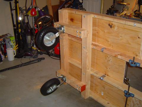
These arrived Wednesday and were quickly mounted. The 4x4->4x4->2x4 pile is starting to look a bit Lincoln Loggy, but it's solid and serves the purpose of offsetting the casters enough to allow for the larger 20" drive wheels to be mounted and still keep the platform level.
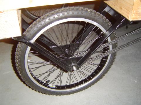
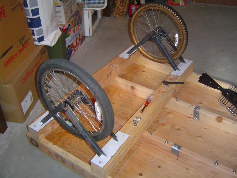
This weekend I focused on the drive wheels. Preliminary tests indicate that I can convert cheap freewheeling bike wheels into fixies with the careful application of red locktite and metal epoxy. I haven't quite mastered the art of getting the ball bearings in place when I reassemble the hubs, but I'm confident that will eventually follow. But with a supply of cheap 20" fixed gear wheels, the last major open design problem was solved, and I just needed to mount them.
The general design for these brackets hasn't really changed since I first worked things out last fall. It was just a matter of working out the specific geometry to get them at the desired height.
After the V brackets were made, they were laid out in situ on the mounting plates bolted to the frame. These were tack-welded and then properly welded in a non-wood-based environment.
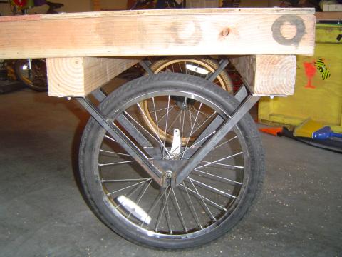
Ta da! I was even able to tip the Kalamazoo upright from being flat on its back, which meant levering it over on one wheel. This has been a concern of mine for the assembly process, and the wheel seemed to handle it without any problems.
It works! It's alarming mobile, actually, if you're standing on it. I might need to think about some kind of e-brake system or remotely removable chocks of some kind.
Coming up soon: final mounting of the pump arm pillow blocks and hopefully a shop trip to get the keyways cut and the pitman arm drilled out. Which would mean a working drive system (if maybe not a working steering/brake system) by next week!
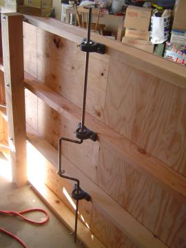
After planning from the beginning to use ~2" pipe, I started to have second thoughts as the time approached. Yes, the pipe would have made for some easy handlebar attachments and central pivot points, using pipe tees. But it would look so cheap. It wouldn't fit the rest of the look at all. And it would make attaching a nice pivot for the pitman arm really annoying. So instead, I got 6 feet of 2" x 4" rectangular steel tubing. (I wanted 1.5" x 4" but they were out. Luckily the extra width doesn't make too much difference to the visual weight in context.)
Last week was spent cutting the arm to shape and drilling the mounting holes for the handlebars and pivot rod. I ended up making all of them 3/4" for convenience. That's a bit narrow for a handlebar, but I'm going to add some grip pads by wrapping leather strips around them later. The arm itself will eventually be painted, probably a dark grey. (All the raw steel will be painted, of course.)
As can be seen in the picture above, the rods were then welded in place. But I'm horrible at welding, you say? True. But Gabriel Cain was kind enough to lend me his MIG set, which sure makes it a hell of a lot easier. I'm really, really going to have to buy one of those for myself.
The mounting of the pillow blocks onto the support struts isn't finalized yet, but it was good enough for a test mount of the pump arm. It works! It pumps! The action is very smooth. Without any resistance, anyway, pumping feels very natural. Was very exciting to stand there and finally get a sense of what piloting this contraption will be like.
Next up: finishing the pillow block mounts, now that I have the arm to get aligned properly. Going to need quite a bit of shimming there. And then it's on to making the drive wheel brackets -- more welding! With those done I'll have the final placement for the wheel chain sprockets, and can get the keyways cut. It's coming together surprisingly quickly, with a good month and a half left. Want to leave plenty of time at the end for road tests and shakedown cruises. Not to mention I need time to work on Laser Medusa Helmet Mark II! Starting to get very excited about the Burn. Attoparsec is going in style this year.
It's been a fairly busy week on the Kalamazoo, but the work was scattered in a bunch of different directions.
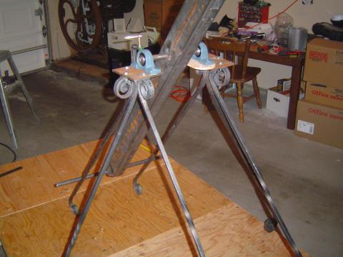
I mounted the pump arm struts finally. This ended up being super fiddly and generally not as perfectly symmetric as I would have liked. But I'm happy enough with the final look -- all those hours at the forge were worth it!
I also cut some plates for mounting the pillow blocks for the pump arm pivot. They will need to be shimmed a bit for their final mounting, and I need to grind some more graceful curves into them.
I had been thinking of forging the drive wheel brackets, so I prototyped one yesterday. It was, simply put, a massive flaming pain in the ass. It's just too big to be worked in my little forge very easily, making it almost impossible to do the kind of fine tuning something like this would need. Starting to think I'll just weld up some very simple brackets out of angle iron.
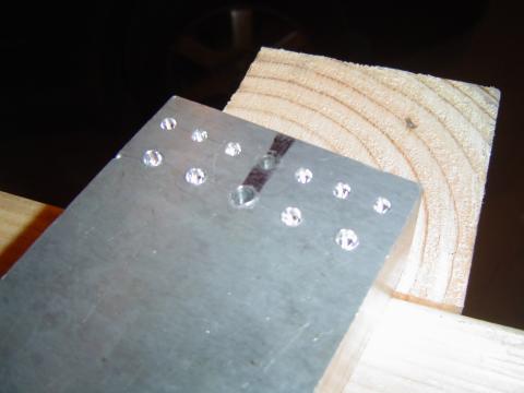
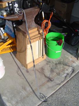
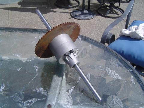
I wanted to start working on the chain drive, but first I needed a chain breaking solution. So I made a anvil for driving the pins out, with divots spaced for both the #35 and #40 chains I'll be dealing with. (No, working with multiple chain sizes was not my idea. The differential came with a #35 sprocket, and bike wheels of course use #40.) Chain sits fairly well with the rivet heads nestled down like that, and the central ones are drilled extra deep so I can drive the pins out with a punch after grinding the head off. Another excellent use for a chunk of Boeing Surplus aluminum!
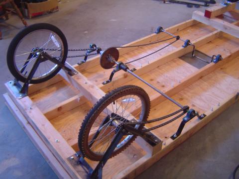
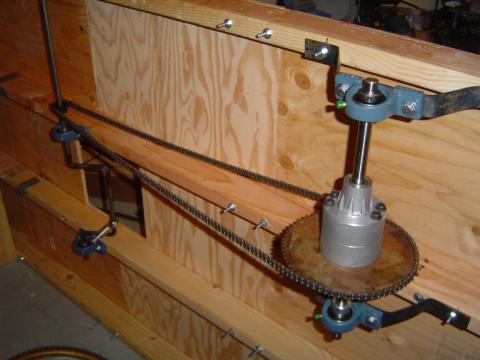
And this is what it got me -- a completed chain drive for the crankshaft to differential connection! The action felt nice, though it can't handle any load of course until I get the keyways cut. A little worried I might have geared things down too far, but swapping out sprockets wouldn't be very hard.
Progress has slowed somewhat, as I started my new job last week. But my vacation time for Burning Man has been confirmed, so work continues!
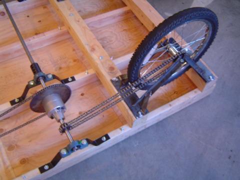
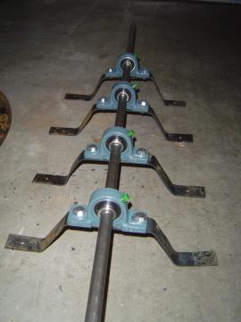
The drive train is completely mounted and trued. The shafts both turn quite nicely in their pillow block bearings, which only took a couple of hours of tweaking. The keyways still need to be cut, but everything else is done.
The forward crankshaft is mounted directly to the frame, but the rear differential shaft needed to sit lower so the chain drive to the rear wheels would clear the 4x4 members. I smithed these rough brackets out of cheap welding steel last week. One of them was a bit wonky, but luckily I only ended up using three of them!
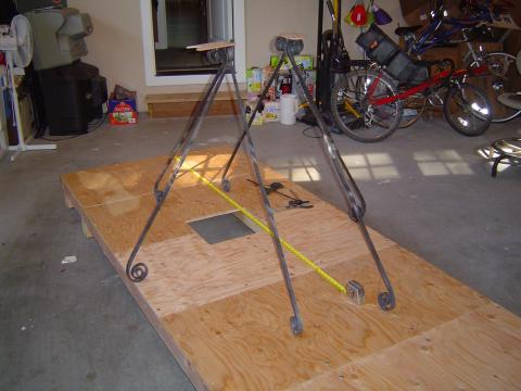
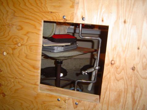
The hole in the platform, allowing the pitman arm to run from the crankshaft to the pump arm. As you can see, the crankshaft itself is no longer quite square, due to some percussive adjustments, but the shaft itself is now. Slightly unpleasing aesthetically, but it's more important that it rotate freely on its bearings than it looks nice. The rod-end bearing will easily handle that small amount of misalignment.
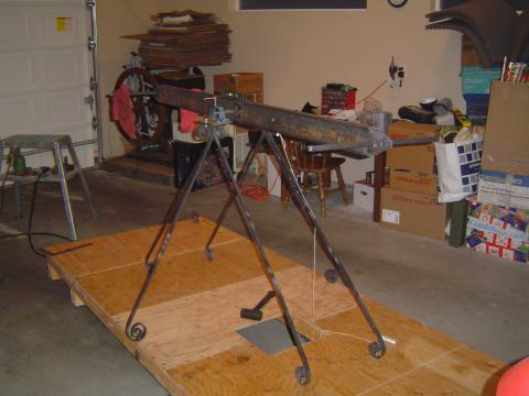
The pump arm struts were also finished, at long last. Ended up taking 5 forge sessions. They still haven't been mounted -- the exact method of mounting has yet to determined -- but this test gives a pretty good idea of how it will work.
Huh, well, okay, maybe there has been quite a bit of work being done. :)
Pulled a marathon forging session this afternoon, and now have 2/3 of the pump arm mounting struts ready to go. I went ahead and curled the ends of one into the decorative spirals, just to see how it looks. I definitely like the look, now I just need to do the remaining 2 struts and figure out the pillow block mounting up top.
I also tried a temp mounting of the crankshaft. I'll need to tweak the crankshaft some more, it's not quite true enough right now. But I'm happy with the mounting, though. Tomorrow I'm going to go ahead and cut out the hole in the decking for the pitman arm.
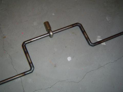
Just finished making the crankshaft for the Kalamazoo.
I ended up just taking a 5 foot section of 1/2" cold roll steel, clamping it up in my leg-vise, heating it up with my gas torch and bending it 90s degrees by hand. Took a couple of adjustments, but I ended up with something very close to true. I left the central U section wide on purpose, to allow room for the rod-end bearing to be added halfway through the process. Making it narrower wouldn't have done much good anyway, as the natural mounting points for the pillow blocks holding the crankshaft are 15.5" apart.
All that remains is to get a keyway cut for mounting the drive sprocket, and the crankshaft will be done.
Yesterday I started forging the mounting braces for the Kalamazoo pump arm. It's great to have the forge running again, but it's going to take time to build up my calluses again. I only got 2 of the 12 ends flattened out nicely, but I did get all of the decorative twists put in at least.
With the pump system under way, I'm working on locking down the design of the drive train itself. Most of the parts (pillow blocks, sprockets and a rod end bearing) are still on their way, but I picked up the differential last month. Made for a lawnmower, it should be perfect for my use here.
Unlike a normal car differential, it is driven inline with the output shafts via the large sprocket. Which really simplifies my design, even if I'm sad not to need a Watt style parallel motion.
The output shafts lack keyways, sadly, and are far too short for my purposes anyway. Currently I'm planning on getting keyways cut and extending them using shaft couplers. I might do that only on one side, but I'm not sure if I can stand that level of asymmetry in the design. I'll need keyways cut for mounting the sprockets anyway -- we're dealing with far too much torque here to get away with set screws!
I was planning on making a nice detailed post here with graphics and everything, describing how differentials work. They're both pleasingly elegant and surprisingly simple. But every time I started outlining that post in my head, I realized I was just paraphrasing a really great video I found once. So instead, I'm just going to post that video. It's from the 30s, but the technology really has't changed much.
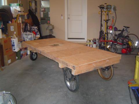
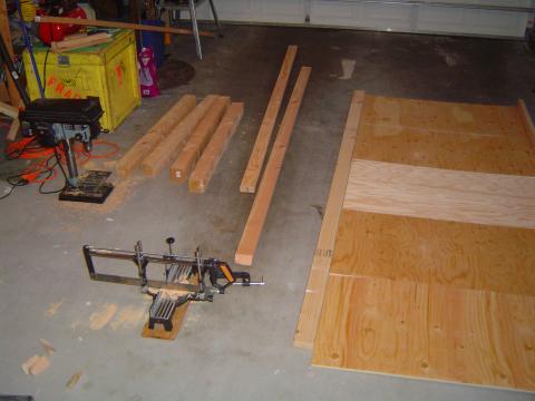
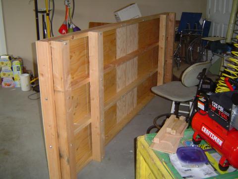
I spent much of yesterday building the Kalamazoo frame.
It took most of the garage space to get it done.
It... ended up a bit bigger than I was imagining.
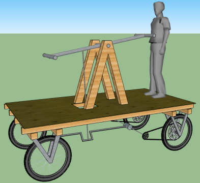
And much more solid. One of my design concerns was CG -- it needs to be operable with just a single driver. (I really want to be able to cruise around camp in it, offering the secondary pump position to those who are interested. Seems like a great way to meet people!) But that means I'll be standing pretty much directly over the rear axle, without no one weighing it down in the front. Accidentally pulling a wheelie in a handcar is an alarming thought! So I did an empirical test this afternoon. I placed spare 2x4s under the frame, and put the whole thing up on a bit of round steel rod as a pivot point about where the axle would be. I jumped up and down on the very end of the platform, and I couldn't lift the far end at all. And that's without all the mass of the pump arm, drive system and wheels. Wheelies: not a danger.
I think the next step will be working on the pump arm supports and some of the drive system brackets, all of which I'm hoping to forge myself out of 1/2" square bar, with some nice decorative flair. Which means I need to get my old forge running again for the first time in 3+ years, yay!
(The following material was previously posted on my other blog. It turns out that the parallel motion won't be needed after all, due to a very convenient differential design, but I thought I'd share it here anyway.)
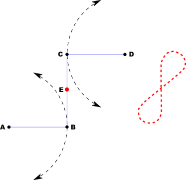
While working on the design for a large Burning Man project, I was faced with a need to have a connecting rod coming off of a rocker arm, but to prevent a very complicated joint it could only pivot in one axis at each end. This was vexing, until I realized that this is not a new problem. No less a figure than James Watt himself faced something similar, when first moving from atmospheric to true steam engines where the piston pushed as well as pulled. The piston rod needed to be kept vertical, while the lever arm it was connected to needed to move in an arc. What to do?
He came up with this, the Watt Linkage. Arms AB and CD pivot about their ends. But on the connecting link CB between them, there is a magic point E (its exact position depends on the ratio of AB to CD) whose motion is something very similar to the analemma-like shape to the right. If you keep the angular displacement of the main arms small compared to their length, E moves almost perfectly vertically. (Technically there is still some horizontal movement, but that's well below anything I'll be caring about. If you want perfection, go with the Peaucellier–Lipkin linkage.)
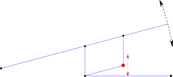
So, that's awesome, but how do you use it for a pump arm like I'm talking about?
You pantograph it! You pantograph the hell out of it! The same parts are there as before, but we've added another two links so that we can use the far corner instead of E. This is a lot easier to attach a piston rod to, and it keeps the tie rod connection close in to the main frame.
Rather charmed with this solution, I went ahead and prototyped it. Good thing, too, because it turns out I didn't really understand it very well to begin with! But further research and testing cleared things up.
As you can see in the video, the motion of E isn't perfectly vertical, because I didn't get the geometry of the linkages particularly great. But you can plainly see how much less its horizontal motion is compared to the pump rod itself. I'm not the world's biggest James Watt fan (everyone hates on Edison, when there are so many assholes in the history of science and technology to choose from!), but he really did make some amazing leaps of design. Props where props are due.
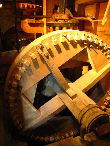
Still on vacation, but I couldn't resist making a post about this. On the way out of DC today we took a bit of a detour and ended up passing by George Washington's grist mill and distillery.
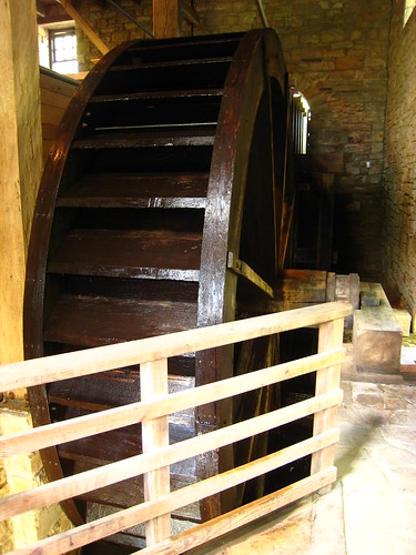
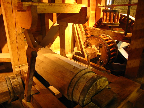
Not knowing anything about it we stopped on a lark, and I'm very glad we did. The distillery was interesting, but the mill really blew me away. Fully operational dual millstone system, run from a nice ~3 meter backshot water wheel. It includes two elevators and a very slick set of sifting and drying mechanisms for partial automation of the process, all of which were part of the original 18th century mill on the site.
The whole thing is stunningly beautiful. The building felt alive while the mill was running, in a way that a primarily metal-based system would be hard to match. Drive shafts crossed the entire building, and large belts drove some of the smaller mechanisms. The workings were taken from an 1818 mill, though the wood cogs are of course much newer. There was an old set piled in one corner, with their teeth worn almost clean through. The old wrought iron linkage rods and even the bolt heads had worn designs stamped into them by some bored smith all those years ago.
(Random flickr images; my camera was acting up today. The others in the collection are nice, too!)
Maker of custom stage props, mad science devices, and kinetic sculptures. Watch our projects evolve here. For a collection of past projects, visit our main site.


