Sunday, June 27, 2010

Shafts and struts

Progress has slowed somewhat, as I started my new job last week. But my vacation time for Burning Man has been confirmed, so work continues!


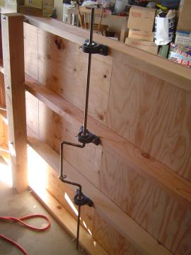
The drive train is completely mounted and trued. The shafts both turn quite nicely in their pillow block bearings, which only took a couple of hours of tweaking. The keyways still need to be cut, but everything else is done.


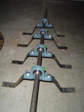
The forward crankshaft is mounted directly to the frame, but the rear differential shaft needed to sit lower so the chain drive to the rear wheels would clear the 4x4 members. I smithed these rough brackets out of cheap welding steel last week. One of them was a bit wonky, but luckily I only ended up using three of them!


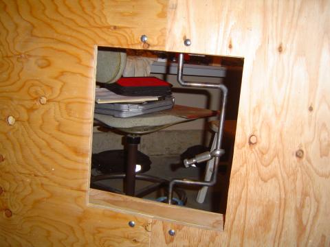
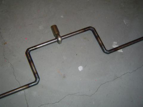
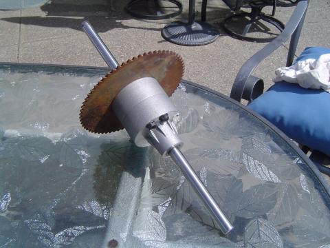
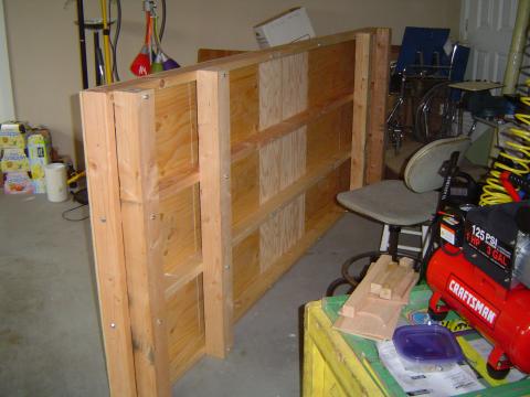
The hole in the platform, allowing the pitman arm to run from the crankshaft to the pump arm. As you can see, the crankshaft itself is no longer quite square, due to some percussive adjustments, but the shaft itself is now. Slightly unpleasing aesthetically, but it's more important that it rotate freely on its bearings than it looks nice. The rod-end bearing will easily handle that small amount of misalignment.


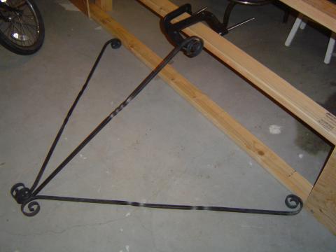
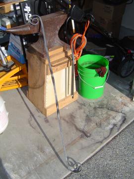
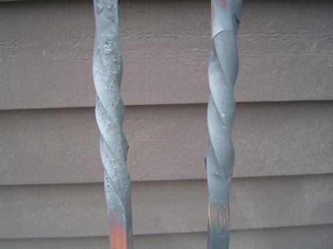
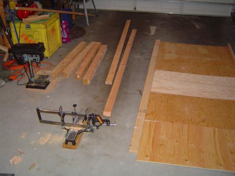
The pump arm struts were also finished, at long last. Ended up taking 5 forge sessions. They still haven't been mounted -- the exact method of mounting has yet to determined -- but this test gives a pretty good idea of how it will work.

Huh, well, okay, maybe there has been quite a bit of work being done. :)

Tuesday, June 15, 2010

Struts and crankshaft mounting

Pulled a marathon forging session this afternoon, and now have 2/3 of the pump arm mounting struts ready to go. I went ahead and curled the ends of one into the decorative spirals, just to see how it looks. I definitely like the look, now I just need to do the remaining 2 struts and figure out the pillow block mounting up top.


I also tried a temp mounting of the crankshaft. I'll need to tweak the crankshaft some more, it's not quite true enough right now. But I'm happy with the mounting, though. Tomorrow I'm going to go ahead and cut out the hole in the decking for the pitman arm.

Monday, June 14, 2010

Crankshaft

Just finished making the crankshaft for the Kalamazoo.


I ended up just taking a 5 foot section of 1/2" cold roll steel, clamping it up in my leg-vise, heating it up with my gas torch and bending it 90s degrees by hand. Took a couple of adjustments, but I ended up with something very close to true. I left the central U section wide on purpose, to allow room for the rod-end bearing to be added halfway through the process. Making it narrower wouldn't have done much good anyway, as the natural mounting points for the pillow blocks holding the crankshaft are 15.5" apart.

All that remains is to get a keyway cut for mounting the drive sprocket, and the crankshaft will be done.

Thursday, June 10, 2010

Kalamazoo progress

Yesterday I started forging the mounting braces for the Kalamazoo pump arm. It's great to have the forge running again, but it's going to take time to build up my calluses again. I only got 2 of the 12 ends flattened out nicely, but I did get all of the decorative twists put in at least.


With the pump system under way, I'm working on locking down the design of the drive train itself. Most of the parts (pillow blocks, sprockets and a rod end bearing) are still on their way, but I picked up the differential last month. Made for a lawnmower, it should be perfect for my use here.


Unlike a normal car differential, it is driven inline with the output shafts via the large sprocket. Which really simplifies my design, even if I'm sad not to need a Watt style parallel motion.

The output shafts lack keyways, sadly, and are far too short for my purposes anyway. Currently I'm planning on getting keyways cut and extending them using shaft couplers. I might do that only on one side, but I'm not sure if I can stand that level of asymmetry in the design. I'll need keyways cut for mounting the sprockets anyway -- we're dealing with far too much torque here to get away with set screws!

I was planning on making a nice detailed post here with graphics and everything, describing how differentials work. They're both pleasingly elegant and surprisingly simple. But every time I started outlining that post in my head, I realized I was just paraphrasing a really great video I found once. So instead, I'm just going to post that video. It's from the 30s, but the technology really has't changed much.

Tuesday, June 1, 2010

Kalamazoo frame

I spent much of yesterday building the Kalamazoo frame.


It took most of the garage space to get it done.


It... ended up a bit bigger than I was imagining.


And much more solid. One of my design concerns was CG -- it needs to be operable with just a single driver. (I really want to be able to cruise around camp in it, offering the secondary pump position to those who are interested. Seems like a great way to meet people!) But that means I'll be standing pretty much directly over the rear axle, without no one weighing it down in the front. Accidentally pulling a wheelie in a handcar is an alarming thought! So I did an empirical test this afternoon. I placed spare 2x4s under the frame, and put the whole thing up on a bit of round steel rod as a pivot point about where the axle would be. I jumped up and down on the very end of the platform, and I couldn't lift the far end at all. And that's without all the mass of the pump arm, drive system and wheels. Wheelies: not a danger.

I think the next step will be working on the pump arm supports and some of the drive system brackets, all of which I'm hoping to forge myself out of 1/2" square bar, with some nice decorative flair. Which means I need to get my old forge running again for the first time in 3+ years, yay!