Another video update! Not much to say that I didn't already say when recording it...
Thursday, July 29, 2010
Sunday, July 25, 2010
Drive train and mounting rungs
This week was a bit disappointing as not one but two shop trips failed to get the keyways cut for the sprockets. My hopes are high for another one this coming Saturday. If that one fails I'm going to have to put out an open plea on the local metal hobbyist list. I'm starting to feel the time pressure, despite still having a full month and really being fairly close to finishing. There are just several other things I need to work on before Burning Man as well as the Kalamazoo, such as the higher power Laser Medusa Helmet upgrade, or converting the old Self-Adjusting Electromechanical Goggles into a more comfortable leather goggle format. Busy, expensive month ahead!
There was still plenty of work done this weekend, though. Despite not having the keyways cut, I assembled the full drive train for the first time, including the drive wheel chains.
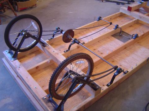
Took some time to adjust the differential shaft mounting to get proper tension on the drive wheel chains. This made the crankshaft chain too slack, but I'm going to add a simple idler for it. I need to order a selection of 1/2" sprockets anyway, as I'm quite sure I'm going to want to adjust the gearing ratio, and there is a very convenient set of mounting bolts available. Easy.
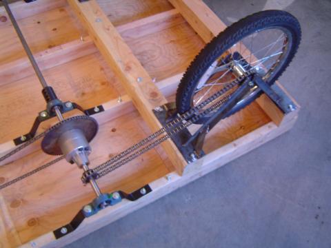
Yeah, I just love how this looks.
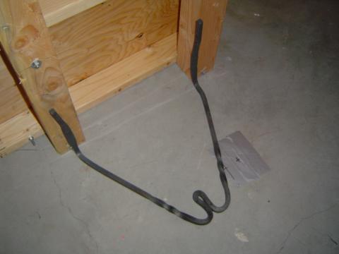
After the test of the platform elevated on all four wheels last week, I started thinking about how to make the Kalamazoo easier to use. It rolled around so easily that mounting it was a bit tricky. I'll probably add some kind of parking brake, but I decided it would also be nice to have a stair at either end so you don't need to make such a big dramatic step to get up on the deck. I spent about an hour with the forge tonight and ended up with a pair of rather handsome, if simple, 1/2" mounting rungs.
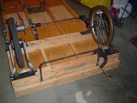
I couldn't resist adding a pretty little twist in the center, where it shouldn't get in the way. I'll bolt them on tomorrow. Which means I'll finally have the 4x4s on the ends removed and can fix the mounting of the decorative 2x4 end plates, which are currently bolted into T-nuts and just aren't very stable. That will be pleasing.
I'm starting to think about lighting for nighttime use. I don't think I want to put el-wire up the pump arm struts, it would just look too tacky during the day. After cruising the lawn lighting section at Lowe's, I'm pondering adding some wrought iron mounting hooks for solar-powered lanterns. Maybe one at each corner, and then one hanging under each pump arm tripod. Not very flashy, but it would go with the look a lot better. I'd still probably put a perimeter loop or two of el-wire around the platform, though, just for safety.
There was still plenty of work done this weekend, though. Despite not having the keyways cut, I assembled the full drive train for the first time, including the drive wheel chains.
Took some time to adjust the differential shaft mounting to get proper tension on the drive wheel chains. This made the crankshaft chain too slack, but I'm going to add a simple idler for it. I need to order a selection of 1/2" sprockets anyway, as I'm quite sure I'm going to want to adjust the gearing ratio, and there is a very convenient set of mounting bolts available. Easy.
Yeah, I just love how this looks.
After the test of the platform elevated on all four wheels last week, I started thinking about how to make the Kalamazoo easier to use. It rolled around so easily that mounting it was a bit tricky. I'll probably add some kind of parking brake, but I decided it would also be nice to have a stair at either end so you don't need to make such a big dramatic step to get up on the deck. I spent about an hour with the forge tonight and ended up with a pair of rather handsome, if simple, 1/2" mounting rungs.
I couldn't resist adding a pretty little twist in the center, where it shouldn't get in the way. I'll bolt them on tomorrow. Which means I'll finally have the 4x4s on the ends removed and can fix the mounting of the decorative 2x4 end plates, which are currently bolted into T-nuts and just aren't very stable. That will be pleasing.
I'm starting to think about lighting for nighttime use. I don't think I want to put el-wire up the pump arm struts, it would just look too tacky during the day. After cruising the lawn lighting section at Lowe's, I'm pondering adding some wrought iron mounting hooks for solar-powered lanterns. Maybe one at each corner, and then one hanging under each pump arm tripod. Not very flashy, but it would go with the look a lot better. I'd still probably put a perimeter loop or two of el-wire around the platform, though, just for safety.
Wednesday, July 21, 2010
Demo and wheel refinements
Surprise! Midweek update!
I finally mounted the pump arm struts again, in order to work out the exact pillow block mounting details. After doing so I took advantage of having the major action working again to film a quick demonstration video. I've been enjoying LostMachine's video updates on the progress of the Pirate Ship for a long time now and recently wondered why I hadn't been doing the same thing. So hopefully look forward to more videos in the future.
I also had the differential on temporarily, to work out exactly where I need keyways cut in the shaft. It'll actually be mounted on the other side for the final assembly, but that doesn't affect the keyway issue any. There's something about the asymmetrical differential placement with its giant sprocket that I just love. Going to look pretty sweet with the drive chains added.
Worried about the strength of the drive wheel brackets due to some pretty bad welds, I added some extra bracing. I also welded on the mounting point for the brakes, as can be seen here. That means I'm done with welding and done with the wheel brackets, woot.

Tomorrow I need to drill the actual mounting holes for the pump arm pillow blocks, now that I have the placement worked out, and maybe try my hand at repacking the hub ball bearings on my fixied drive wheel. (I finally looked up some guides, and my initial instinct was correct: use loads and loads of grease to holds the balls in place!) If that works, I'll apply the same massive adhesive hack to the other drive wheel.
I finally mounted the pump arm struts again, in order to work out the exact pillow block mounting details. After doing so I took advantage of having the major action working again to film a quick demonstration video. I've been enjoying LostMachine's video updates on the progress of the Pirate Ship for a long time now and recently wondered why I hadn't been doing the same thing. So hopefully look forward to more videos in the future.
I also had the differential on temporarily, to work out exactly where I need keyways cut in the shaft. It'll actually be mounted on the other side for the final assembly, but that doesn't affect the keyway issue any. There's something about the asymmetrical differential placement with its giant sprocket that I just love. Going to look pretty sweet with the drive chains added.
Worried about the strength of the drive wheel brackets due to some pretty bad welds, I added some extra bracing. I also welded on the mounting point for the brakes, as can be seen here. That means I'm done with welding and done with the wheel brackets, woot.
Tomorrow I need to drill the actual mounting holes for the pump arm pillow blocks, now that I have the placement worked out, and maybe try my hand at repacking the hub ball bearings on my fixied drive wheel. (I finally looked up some guides, and my initial instinct was correct: use loads and loads of grease to holds the balls in place!) If that works, I'll apply the same massive adhesive hack to the other drive wheel.
Monday, July 19, 2010
The wheels on the Kalamazoo go round and round
The theme of this week was: wheels!
After much thought and research and procrastination, I finally decided that making my own casters out of bike wheels was not a good use of my time. Unfortunately, the market for very large pneumatic casters is pretty much non-existent. If you want anything larger than a 12" diameter, you're going to have to pay hundreds of dollars. So, 12" casters it was.
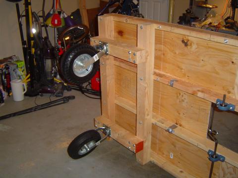
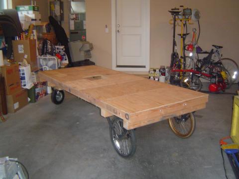
These arrived Wednesday and were quickly mounted. The 4x4->4x4->2x4 pile is starting to look a bit Lincoln Loggy, but it's solid and serves the purpose of offsetting the casters enough to allow for the larger 20" drive wheels to be mounted and still keep the platform level.
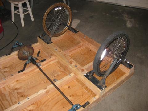
This weekend I focused on the drive wheels. Preliminary tests indicate that I can convert cheap freewheeling bike wheels into fixies with the careful application of red locktite and metal epoxy. I haven't quite mastered the art of getting the ball bearings in place when I reassemble the hubs, but I'm confident that will eventually follow. But with a supply of cheap 20" fixed gear wheels, the last major open design problem was solved, and I just needed to mount them.
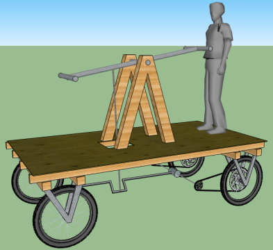
The general design for these brackets hasn't really changed since I first worked things out last fall. It was just a matter of working out the specific geometry to get them at the desired height.
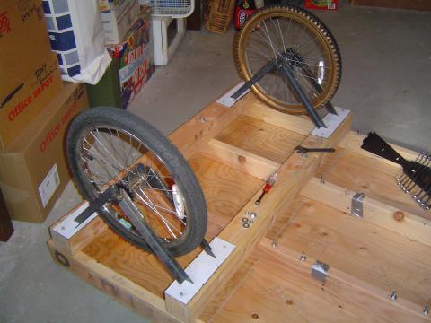
After the V brackets were made, they were laid out in situ on the mounting plates bolted to the frame. These were tack-welded and then properly welded in a non-wood-based environment.
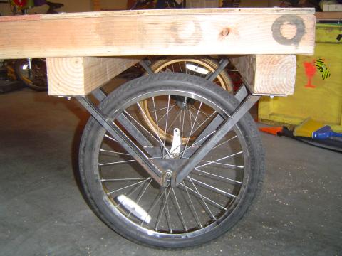
Ta da! I was even able to tip the Kalamazoo upright from being flat on its back, which meant levering it over on one wheel. This has been a concern of mine for the assembly process, and the wheel seemed to handle it without any problems.
It works! It's alarming mobile, actually, if you're standing on it. I might need to think about some kind of e-brake system or remotely removable chocks of some kind.
Coming up soon: final mounting of the pump arm pillow blocks and hopefully a shop trip to get the keyways cut and the pitman arm drilled out. Which would mean a working drive system (if maybe not a working steering/brake system) by next week!
After much thought and research and procrastination, I finally decided that making my own casters out of bike wheels was not a good use of my time. Unfortunately, the market for very large pneumatic casters is pretty much non-existent. If you want anything larger than a 12" diameter, you're going to have to pay hundreds of dollars. So, 12" casters it was.
These arrived Wednesday and were quickly mounted. The 4x4->4x4->2x4 pile is starting to look a bit Lincoln Loggy, but it's solid and serves the purpose of offsetting the casters enough to allow for the larger 20" drive wheels to be mounted and still keep the platform level.
This weekend I focused on the drive wheels. Preliminary tests indicate that I can convert cheap freewheeling bike wheels into fixies with the careful application of red locktite and metal epoxy. I haven't quite mastered the art of getting the ball bearings in place when I reassemble the hubs, but I'm confident that will eventually follow. But with a supply of cheap 20" fixed gear wheels, the last major open design problem was solved, and I just needed to mount them.
The general design for these brackets hasn't really changed since I first worked things out last fall. It was just a matter of working out the specific geometry to get them at the desired height.
After the V brackets were made, they were laid out in situ on the mounting plates bolted to the frame. These were tack-welded and then properly welded in a non-wood-based environment.
Ta da! I was even able to tip the Kalamazoo upright from being flat on its back, which meant levering it over on one wheel. This has been a concern of mine for the assembly process, and the wheel seemed to handle it without any problems.
It works! It's alarming mobile, actually, if you're standing on it. I might need to think about some kind of e-brake system or remotely removable chocks of some kind.
Coming up soon: final mounting of the pump arm pillow blocks and hopefully a shop trip to get the keyways cut and the pitman arm drilled out. Which would mean a working drive system (if maybe not a working steering/brake system) by next week!
Monday, July 12, 2010
Pump arm
The pump arm is done!
After planning from the beginning to use ~2" pipe, I started to have second thoughts as the time approached. Yes, the pipe would have made for some easy handlebar attachments and central pivot points, using pipe tees. But it would look so cheap. It wouldn't fit the rest of the look at all. And it would make attaching a nice pivot for the pitman arm really annoying. So instead, I got 6 feet of 2" x 4" rectangular steel tubing. (I wanted 1.5" x 4" but they were out. Luckily the extra width doesn't make too much difference to the visual weight in context.)

Last week was spent cutting the arm to shape and drilling the mounting holes for the handlebars and pivot rod. I ended up making all of them 3/4" for convenience. That's a bit narrow for a handlebar, but I'm going to add some grip pads by wrapping leather strips around them later. The arm itself will eventually be painted, probably a dark grey. (All the raw steel will be painted, of course.)
As can be seen in the picture above, the rods were then welded in place. But I'm horrible at welding, you say? True. But Gabriel Cain was kind enough to lend me his MIG set, which sure makes it a hell of a lot easier. I'm really, really going to have to buy one of those for myself.
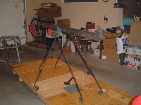
The mounting of the pillow blocks onto the support struts isn't finalized yet, but it was good enough for a test mount of the pump arm. It works! It pumps! The action is very smooth. Without any resistance, anyway, pumping feels very natural. Was very exciting to stand there and finally get a sense of what piloting this contraption will be like.
Next up: finishing the pillow block mounts, now that I have the arm to get aligned properly. Going to need quite a bit of shimming there. And then it's on to making the drive wheel brackets -- more welding! With those done I'll have the final placement for the wheel chain sprockets, and can get the keyways cut. It's coming together surprisingly quickly, with a good month and a half left. Want to leave plenty of time at the end for road tests and shakedown cruises. Not to mention I need time to work on Laser Medusa Helmet Mark II! Starting to get very excited about the Burn. Attoparsec is going in style this year.
After planning from the beginning to use ~2" pipe, I started to have second thoughts as the time approached. Yes, the pipe would have made for some easy handlebar attachments and central pivot points, using pipe tees. But it would look so cheap. It wouldn't fit the rest of the look at all. And it would make attaching a nice pivot for the pitman arm really annoying. So instead, I got 6 feet of 2" x 4" rectangular steel tubing. (I wanted 1.5" x 4" but they were out. Luckily the extra width doesn't make too much difference to the visual weight in context.)
Last week was spent cutting the arm to shape and drilling the mounting holes for the handlebars and pivot rod. I ended up making all of them 3/4" for convenience. That's a bit narrow for a handlebar, but I'm going to add some grip pads by wrapping leather strips around them later. The arm itself will eventually be painted, probably a dark grey. (All the raw steel will be painted, of course.)
As can be seen in the picture above, the rods were then welded in place. But I'm horrible at welding, you say? True. But Gabriel Cain was kind enough to lend me his MIG set, which sure makes it a hell of a lot easier. I'm really, really going to have to buy one of those for myself.
The mounting of the pillow blocks onto the support struts isn't finalized yet, but it was good enough for a test mount of the pump arm. It works! It pumps! The action is very smooth. Without any resistance, anyway, pumping feels very natural. Was very exciting to stand there and finally get a sense of what piloting this contraption will be like.
Next up: finishing the pillow block mounts, now that I have the arm to get aligned properly. Going to need quite a bit of shimming there. And then it's on to making the drive wheel brackets -- more welding! With those done I'll have the final placement for the wheel chain sprockets, and can get the keyways cut. It's coming together surprisingly quickly, with a good month and a half left. Want to leave plenty of time at the end for road tests and shakedown cruises. Not to mention I need time to work on Laser Medusa Helmet Mark II! Starting to get very excited about the Burn. Attoparsec is going in style this year.
Tuesday, July 6, 2010
Brackets and chain
It's been a fairly busy week on the Kalamazoo, but the work was scattered in a bunch of different directions.
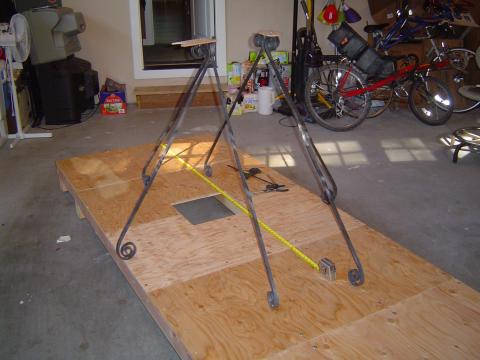
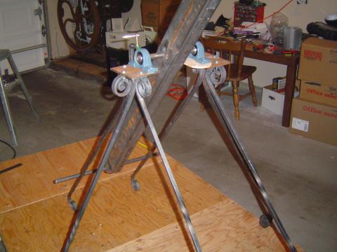
I mounted the pump arm struts finally. This ended up being super fiddly and generally not as perfectly symmetric as I would have liked. But I'm happy enough with the final look -- all those hours at the forge were worth it!
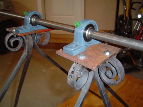
I also cut some plates for mounting the pillow blocks for the pump arm pivot. They will need to be shimmed a bit for their final mounting, and I need to grind some more graceful curves into them.
I had been thinking of forging the drive wheel brackets, so I prototyped one yesterday. It was, simply put, a massive flaming pain in the ass. It's just too big to be worked in my little forge very easily, making it almost impossible to do the kind of fine tuning something like this would need. Starting to think I'll just weld up some very simple brackets out of angle iron.
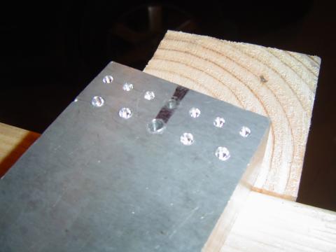
I wanted to start working on the chain drive, but first I needed a chain breaking solution. So I made a anvil for driving the pins out, with divots spaced for both the #35 and #40 chains I'll be dealing with. (No, working with multiple chain sizes was not my idea. The differential came with a #35 sprocket, and bike wheels of course use #40.) Chain sits fairly well with the rivet heads nestled down like that, and the central ones are drilled extra deep so I can drive the pins out with a punch after grinding the head off. Another excellent use for a chunk of Boeing Surplus aluminum!
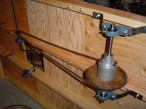
And this is what it got me -- a completed chain drive for the crankshaft to differential connection! The action felt nice, though it can't handle any load of course until I get the keyways cut. A little worried I might have geared things down too far, but swapping out sprockets wouldn't be very hard.
I mounted the pump arm struts finally. This ended up being super fiddly and generally not as perfectly symmetric as I would have liked. But I'm happy enough with the final look -- all those hours at the forge were worth it!
I also cut some plates for mounting the pillow blocks for the pump arm pivot. They will need to be shimmed a bit for their final mounting, and I need to grind some more graceful curves into them.
I had been thinking of forging the drive wheel brackets, so I prototyped one yesterday. It was, simply put, a massive flaming pain in the ass. It's just too big to be worked in my little forge very easily, making it almost impossible to do the kind of fine tuning something like this would need. Starting to think I'll just weld up some very simple brackets out of angle iron.
I wanted to start working on the chain drive, but first I needed a chain breaking solution. So I made a anvil for driving the pins out, with divots spaced for both the #35 and #40 chains I'll be dealing with. (No, working with multiple chain sizes was not my idea. The differential came with a #35 sprocket, and bike wheels of course use #40.) Chain sits fairly well with the rivet heads nestled down like that, and the central ones are drilled extra deep so I can drive the pins out with a punch after grinding the head off. Another excellent use for a chunk of Boeing Surplus aluminum!
And this is what it got me -- a completed chain drive for the crankshaft to differential connection! The action felt nice, though it can't handle any load of course until I get the keyways cut. A little worried I might have geared things down too far, but swapping out sprockets wouldn't be very hard.
Subscribe to:
Posts (Atom)